
Pricing Plans
Go with the right one
About Us
M/S Stability pre-stressing systems pty-ltd (SPS) is a major Australian company in post-tension technology pre-stressing services.

Services provided by M/S SPS:
- Manufacturing , design, supply, and installation for post tension system
- Piling work,
- concrete protection, maintenance and Repairs
- Value engineering, cost management
- Mono &multi strands post tension and slab post tension
SPS. Is supplying of post-tension materials (Temove fabricated locally in house) and equipments with the high quality and most competitive price.

SPS employees: SPS have a leader staff of engineers and technicians to make full support to our customer’s requirements.
-our quality control division is allowing us to have the highest quality of the materials.
SPS: Supply post-tension materials to several countries Australia such as Europe (Belgium), meddle east (UAE, KSA, Qatar & Oman) and Africa (Algeria, Egypt, Sudan)
SPS : has designed supplied and executed several projects over the world with the high quality and performance
What is Post Tension
Pre-stressed concrete is a method for overcoming concrete‘s natural weakness in tension. It can be used to produce beams,floors or bridges with a longer span than is practical with ordinary reinforced concrete. Prestressing tendons (generally of hightensile steel cable or rods) are used to provide a clamping load which produces a compressive stress that balances the tensile stress that the concrete compression member would otherwise experience due to a bending load. Traditional reinforced concrete is based on the use of steel reinforcement bars, rebars, inside poured concrete.
Prestressing can be accomplished in three ways: pre-tensioned concrete, and bonded or unbonded post-tensioned concrete.
Although post-tensioning systems require specialized knowledge and expertise to fabricate, assemble and install,the concept is easy to explain. Imagine a series of woodenblocks with holes drilled through them, into which a rubberband is threaded. If one holds the ends of the rubber band,the blocks will sag. Post-tensioning can be demonstrated byplacing wing nuts on either end of the rubber band andwinding the rubber band so that the blocks are pushedtightly together. If one holds the wing nuts after winding,the blocks will remain straight. The tightened rubber band iscomparable to a post-tensioning tendon that has beenstretched by hydraulic jacks and is held in place bywedge-type anchoring devices.
BENEFITS
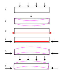
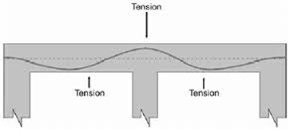
To fully appreciate the benefits of post-tensioning, it is helpful to know a little bit about concrete. Concrete is very strong in compression but weak in tension, i.e. it willcrack when forces act to pull it apart. In conventional concrete construction, if a load such as the cars in a parking garage is applied to a slab or beam, the beam will tend to deflect or sag. This deflection will cause the bottom of the beam to elongate slightly.
Even a slight elongation is usually enough to cause cracking. Steel reinforcing bars (“rebar”) are typically embedded in the concrete as tensile reinforcement to limit the crack widths. Rebar is what is called “passive” reinforcement however; it does not carry any force until the concrete has already deflected enough to crack. Post-tensioning tendons, on the other hand, are considered “active” reinforcing. Because it is prestressed, the steel is effective as reinforcement even though the concrete may not be cracked. Post-tensioned structures can be designed to have minimal deflection and cracking, even under full load.
ADVANTAGES/APPLICATIONS
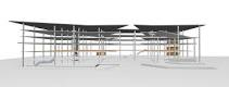
There are post-tensioning applications in almost all facets of construction. In building construction, post-tensioning allows longer clear spans, thinner slabs, fewer beams and
more slender, dramatic elements. Thinner slabs mean less concrete is required. In addition, it means a lower overall building height for the same floor-to-floor height. Post- tensioning can thus allow a significant reduction in building weight versus a conventional concrete building with the same number of floors. This reduces the foundation load and can be a major advantage in seismic areas. A lower building height can also translate to considerable savings in mechanical systems and façade costs. Another advantage of post-tensioning is that beams and slabs can be continuous, i.e. a single beam can run continuously from one end of the building to the other. Structurally, this is much more efficient than having a beam that just goes from one column to the next.
Post-tensioning is the system of choice for parking structures since it allows a high degree of flexibility in the column lay-out, span lengths and ramp configurations. Post-tensioned parking garages can be either stand-alone structures or one or more floors in an office or residential building. In areas where there are expansive clays or soils with low bearing capacity, post-tensioned slabs-on-ground and mat founda- tions reduce problems
with cracking and differential settle-ment. Post-tensioning allows bridges to be built to very demanding geometry requirements, including complex curves, variable superelevation and significant grade changes. Post-tensioning also allows extremely long span bridges to be constructed without the use of temporary intermediate supports. This minimizes the impact on the environment and avoids disruption to water or road traffic below. In stadiums, post-tensioning allows long clear spans and very creative architecture. Post-tensioned rock and soil anchors are used in tunneling and slope stabilization and as tie-backs for
Materials
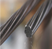
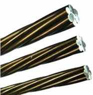
Post-Tensioning Strand
Strand is manufactured from 7 individual cold-drawn wires, outer wires helically wound around one center wire (king wire). The mechanical properties of the strand as well as its corrosion protection are most important to SBS. Strand coatings do not affect the anchorage’s capacity or efficiency
For improved corrosion protection, we offer systems using polyethylene (PE) or polypropylene (PP) ducts.
PT strand is available in several diameters ranging from .250 in. to .600 in. For most post-tensioning applications, the standard size strand is either the .500 in. or .600 in. diameter (ASTM).
Recommended design values:
- Spacing of tendon supports 0.6 to 1.5 m
- Minimal radius 2.5 m
- Friction coefficient µ = 0.06
- Unintentional angular deviation per unit length k=µ*(, = 0.0005 m-1
Post-Tensioning Strand
code / specification | ASTM A 416 | ASTM A 416 | ||||
type | 0.5″ (13mm) | 0.6″ (15mm) | 0.5″ (13mm) | 0.6″ (15mm) | ||
yield strength fy1 | (ksi) | 243 | 243 | (N/mm2) | 1,670 | 1,670 |
ultimate strength fu | (ksi) | 270 | 270 | (N/mm2) | 1,860 | 1,860 |
nom. diameter | (in) | 0.5 | 0.6 | (mm) | 12.7 | 15.24 |
cross-sectional area | (in2) | 0.153 | 0.217 | (mm2) | 98.71 | 140 |
weight | (lbs/ft) | 0.52 | 0.74 | (kg/m) | 0.775 | 1.102 |
ultimate load | (kips) | 41.3 | 58.6 | (kN) | 183.7 | 260.7 |
modulus of elasticity | (ksi) | 28,000 | 28,000 | (N/mm2) | 195,000 | 195,000 |
relaxation after 2 | (%) | 2.5 | 2.5 | (%) | 2.5 | 2.5 |
1) yield measured at 1% extension under load
2) applicable for relaxation class 2 according to Eurocode prEN 10138/BS 5896: or low relaxation complying with ASTM A 416, respectively
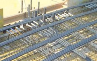
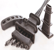
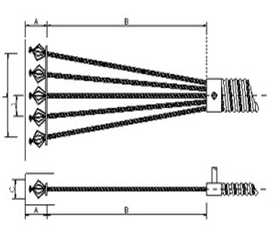
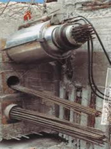
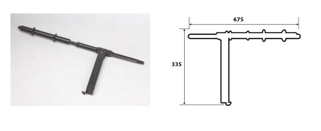
Views of monostrand bundles at anchorage and over support. Monostrands can be supplied from the workshop already bundled and placed in this form. A monostrand bundle may comprise a group of 2, 3 or at most 4 strands
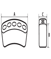
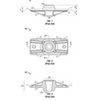
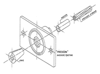
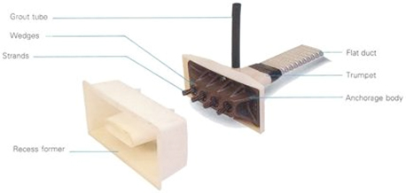
Flat Anchorage SBSF
The Flat Anchorage of max. 4-0.62″ strands in one plane to deviate into one oval duct is designed to be installed in thin members such as transverse Post-Tensioning of the top slab of box-girder bridges and prestressed flat slabs.
Tendon Size | 3_ 0.5″(13) | 4_ 0.5″(13) | 5_ 0.5″(13) 4_ 06” (15) |
|
|
|
|
|
|
|
|
|
| 3_ 0.6″(15) |
Flat Anchorage F | 7.6 \ 190 | 9.0 \ 230 | 10 \ 260 | 9 \ 230 | ||||||||||
E | 4 \ 100 | 4 \ 100 | 4.2 \ 105 | 4.2 \ 105 | ||||||||||
Transition K | 10 \ 250 | 111/4 \ 285 | 12-1/4 \ 310 | 11-1/4 \ 285
| ||||||||||
C | 5.8 \ 145 | 7.0 \ 175 | 8.2 \ 205 | 7.8 \ 195 | ||||||||||
Pocket Former A | 3-1/4 \ 78 | 3-1/4 \ 78 | 3-1/4 \ 78 | 3-1/4 \ 78 | ||||||||||
B | 6-1/4 \ 155 | 7-7/8 \ 190 | 8-3/8 \ 210 | 7-7/8 \ 190 | ||||||||||
D | 3-5/8 \ 90 | 3-5/8 \ 90 | 3-5/8 \ 90 | 3-5/8 \ 90 | ||||||||||
NO OF STRANDS | 3 | 4 | 4 \ 5 | 3 | ||||||||||
STRAND DIAMTER | 0.5″ \12.7 | 0.5″ \12.7 | 0.6″ \15.2 |
All dimensions are nominal and are expressed in inch \ mm.
Post tensioning flat slab anchorage offers a cost effective and efficient solution for the construction industry. At STS we STOCKand supply a wide variety of flat anchorage components to suit 13mm (0.5”), 15mm (0.6”) and 15.7mm (0.62”) strand diameters, with up to 5 strands requirement. At STS we can also help you in the design, manufacture and supply of any of your specific product requirements with competitive project cycle times. flat slab anchors are manufactured in grey iron to meet the AS1830 Australian Standard. The wedge block is manufactured from ductile iron that complies with the AS1831 Australian Standard.
The production of anchorage products is closely monitored by our quality system and material test certificates can be supplied with each delivery upon request. Anchorages and wedges are manufactured in different ways for different applications. They follow the American Concrete Institute (ACI) code 318, which fundamentally states that the anchorage system is guaranteed up to 95% of the breaking strength of the strand (TU) (ACI). For projects that require higher tensile strength
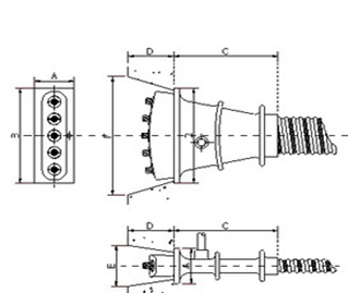
Bond Head Anchorage SPSF/SPSD
Primarily used with prefabricated tendons, it is also possible to fabricate this anchorage on site. The strand wires are plastically deformed to ensure a safe load transfer up to ultimate capacity in the area of the bond head proven in static as well as in dynamic applications. Depending on the boundary conditions, either a rather flat or a bulky bond head anchorage pattern is available
Bond Head Anchorage – technical Details
stressing anchorage | dead end anchorage | ||
accessible | not accessible |
| |
no | no | yes |
|
coupling | ultimate load 0.5 [kips/kN] | ||
from | to |
| |
no | 41.3/184 | 1,115/4,961 |
|
coupling | ultimate load 0.6 [kips/kN] | ||
from | to |
| |
no | 58.6/261 | 1,582/7,037 |
|
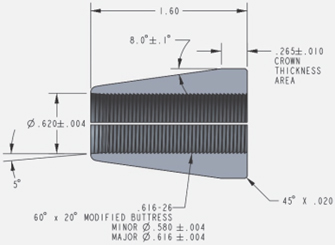
Anchor Wedge
Definition of Wedge: Pieces of tapered high-strength heat-treated steel with serrations (teeth) that penetrate the prestressing steel during transfer of prestressing force. Some anchorage systems use two-part wedges and some use three-part wedges
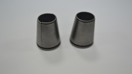
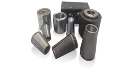
Wedges sit in the anchor and grip onto the strand to hold it in place .They are manufactured in two- and three- parts, both of which we tested. The wedge is manufactured with the material complying with the AS1443 Australian standard
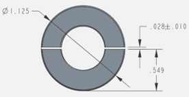
Wedge Manufacturing Process
PT anchor wedges play a very significant role by controlling the stress transfer from the strand to the anchor housing. The typical manufacturing process for the wedges involves the following general steps:
1) Select round bar stock of proper diameter and steel grade;
2) Produce a wedge cone by forming the proper taper angle on the outside body of the bar stock over an appropriate length at the end;
3) Drill/bore a center hole through the wedge cone in preparation for the wedge teeth;
4) Cut the wedge cone to proper length;
5) Manufacture teeth into the center of the wedge cone (usually by tapping);
6) Split (section) wedge cone into two pieces (for a two-piece wedge) with proper crown thickness;
7) Heat treat final properties into the wedge to achieve proper surface hardness, case depth, and core hardness;
8) Verify taper angle of finished sectioned wedge piece in relationship to the teeth profile;
and
9) Verify cross section thickness at the crown of finished sectioned wedge piece.
4- Galvanized duct
For tendons containing a single post-tensioning bar the internal duct diameter should be at least 6mm (¼ in) greater than the maximum outside dimension of the bar..
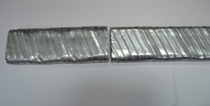
Tendons in standard corrugated steel flat ducts
Recommended design values:
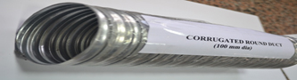
Tendons in corrugated polyethylene or polypropylene ducts
Recommended design values:
Spacing of tendon support
Minimal radius 2.5 m (vertical)
6.0 m (horizontal)
Friction coefficient µ = 0.14
Unintentional angular deviation per unit length k=µ*(, = 0.0010
Ducts are spirally wound to the necessary diameter from strip steel with a minimum wall thickness of
0.45mm (26-gauge) for ducts less than 66mm (2-5/8 in) diameter or 0.6mm (24-gauge) for ducts of greater diameter. The strip steel should be galvanized to ASTM A653 with a coating weight of G90. Ducts should be
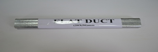
Tendons in standard corrugated steel flat ducts
Recommended design values:
Spacing of tendon support 0.8 to 1.0 m
Minimal radius 2.5 m (vertical)
6.0 m (horizontal) Friction coefficient µ =0.2
Unintentional angular deviation per unit length k= µ*(, = 0.0008
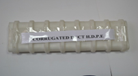
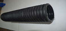
manufactured with welded or interlocking seams with sufficient rigidity to maintain the correct profile between supports during concrete placement Ducts should also be able to flex without crimping or flattening. Joints between sections of duct and between ducts and anchor components should be made with positive, metallic connections that provide a smooth interior alignment with no lips or abrupt angle changes.
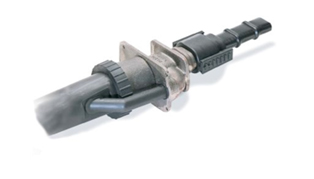
Couplers
The couplers enable a new cable to be connected onto a previously installed and stressed cable. Different degrees of corrosion protection can be achieved:
– high degree of corrosion protection with fully encapsulated strands
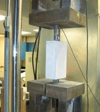
- 1.1 testing
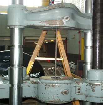
The first set of testing we performed were static (monotonic) stress tests on an analog universal testing machine at Fritz lab. These initial tests were performed with strand and anchors leftover from previous testing at the Advanced Technology for Large Structural Systems (ATLSS) lab. The materials were not outdated, yet their condition was somewhat in question which is why we tried to make a clear distinction for these tests in our data. Before we could begin any kind of testing, we made sure that the proper safety precautions were taken. When taking the strand to its breaking strength, there is the risk of the wedges popping out of the anchor. To account for that we put a cover over the ends to control any pieces that came loose (Figure 3.6).
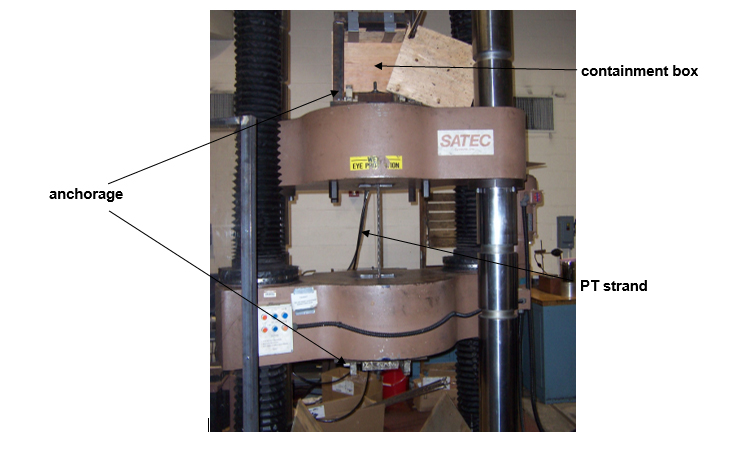
PT strand |
anchorage (hidden by crossheads) |
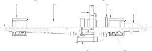
The basic setup for the testing was a five foot segment of PT strand that was anchored on both of the crossheads of the universal testing machine at Fritz lab (Figure 3.5). The wedges were hand-set to be as level as possible before adding tension to the strand. After covering up the anchors to contain any flying debris, we added some tension to seat the wedges into the anchors. We tried to achieve a four to six minute elongation period (between 10 and 15 kips/min load rate), but for these tests we could only rely on knobs to fine tune the crosshead displacement and a stopwatch to monitor the time. The strands were loaded until at least one of the wires ruptured, and at that point the breaking strength and time were recorded. That process was repeated for several trials.
The next phase of testing was completed with new strand, anchors and wedges provided by Dywidag-Systems International (DSI). Testing began at Fritz lab with the same procedure as before, but we ended up moving our testing to the SATEC universal testing machine in the ATLSS lab. The SATEC machine can be more controlled by a computer, and it also records data straight from the machine. Stress, head displacement, and time were the parameters that we monitored during our testing. To ensure the wedges set properly a “soft zone” was implemented, in which the crossheads displaced at a rate of .1 in/min until there was 100 lbs. tension in the strand. After the “soft zone,” we programmed the machine to load the strand at a rate of 12.00 kips/min for the first three tests, and 9.00 kips/min for the next three tests. As an added safety precaution, there was also a break detection mechanism which would stop the machine if there was a drop of at least 10% of the load past the 5000 lb. stress level. The tests were physically set up the same way as in Fritz lab (Figure 3.6).
To perform proper tensile tests to obtain a stress-strain curve of the strand, we had to find a new way of anchoring the ends. The conventional anchor-wedge system is only guaranteed to 95%TU, so we would be missing a very important part of the curve using that system. As an attempt to solve this problem, we turned to a cold-socketing compound called Wirelock. This material is
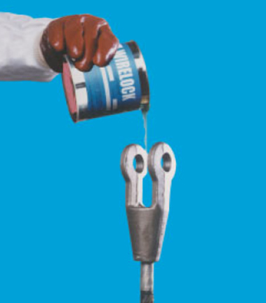
composed of a liquid resin and a granular compound (Millfield). When mixed and poured into the socket around a wire, the two components quickly form a solid resin that is greatly resistant to compressive forces (Figure 3.7). The key to getting correct results from the Wirelock is the preparation of the strand or wire that you are bonding to. The resin is primarily used on wire ropes, which are made up of many finer wires spun around each other. Splaying the wires out and unraveling them so they appear like a broom maximizes the surface area of wire for the resin to bond to and allows for a strong connection between the
socket |
wire rope and the Wirelock.
Figure 3.7 Wirelock being pouring into a socket
As a an alternative to Wirelock, we also tried using old grips that were found at Fritz lab. A grip is composed of two copper plates about six inches long that get compressed around the wire. The compressive force comes from inserts in the crossheads of the universal testing machine that create a wedge-like effect on the plates.
Equipments
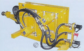
Pushing and Grouting Equipment
type | pushing force | pushing speed | weight | dimensions LxWxH | hydraulic pumps | amp draw |
kips | ft/s | lbs | in | |||
SBSP 8-1 | 0.88 | 20 | 309 | 55×13.8×20 | ZP57* | 44 |
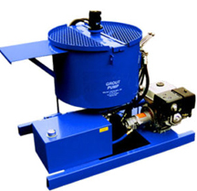
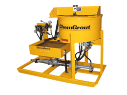
grouting equipment | max. injection pressure | capacity | weight | dimensions LxWxH |
SBSG600 Colloidal | psi | gpm | pounds | in |
– with Moyno pumps | 250 | 20 | 1,100 | 90x37x63 |
– with Piston Pump (1,000 psi) | 1,000 | 20 | 1,725 | 90x37x63 |
Note: Air pressure required to operate is 280 cfm@100 psi

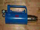
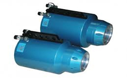
Hydraulic Jacks
jack type 59 … (0.5″) | 01 | 02 | 03 | 04 | 05 | 06 | 07 | 08 | 09 | 12 | 15 | 19 | 27 | 37 |
Mono 0.6 | * | |||||||||||||
HoZ 950 | * | * | * | * | ||||||||||
HoZ 1,700 | * | * | * | * | ||||||||||
HoZ 3,000 | * | * | * | |||||||||||
HoZ 4,000 | ||||||||||||||
Tensa 260 | ||||||||||||||
Tensa 3,000 | ||||||||||||||
Tensa 4,800 | ||||||||||||||
Tensa 6,800 | * | |||||||||||||
Tensa 8,600 |
jack type 68 … (0.6″) | 01 | 02 | 03 | 04 | 05 | 06 | 07 | 08 | 09 | 12 | 15 | 19 | 27 | 37 |
Mono 0.6 | * | |||||||||||||
HoZ 950 | * | * | * | |||||||||||
HoZ 1,700 | * | * | * | |||||||||||
HoZ 3,000 | * | * | * | |||||||||||
HoZ 4,000 | * | * | ||||||||||||
Tensa 260 | * | * | * | |||||||||||
Tensa 3,000 | * | * | * | |||||||||||
Tensa 4,800 | * | * | ||||||||||||
Tensa 6,800 | * | |||||||||||||
Tensa 8,600 | * |
jack type 1) | length L3 | diameter D | stroke | piston area | capacity 2) | weight |
| [in / mm] | [in / mm] | [in / mm] | [in2 / cm2] | [kip / kN] | [lbs / kg] |
Mono 0.6 | 21.5 / 546 | n/a | 8.5 / 213 | 7.95 / 51.3 | 60 / 267 | 52 / 24 |
HoZ 950 | 24.45 / 621 | 8 / 203 | 3.94 / 100 | 25.1 / 162 | 218 / 972 | 144 / 65 |
HoZ 1,700 | 31.6 / 803 | 11 / 280 | 5.9 / 150 | 46.26 / 298.45 | 392 / 1,745 | 354 / 160 |
HoZ 3,000 | 44.76 / 1,137 | 15.16 / 385 | 9.84 / 250 | 78.9 / 509 | 687 / 3,054 | 884 / 400 |
HoZ 4,000 | 50 / 1,271 | 18.98 / 482 | 9.84 / 250 | 138.7 / 894.6 | 945 / 4,204 | 1,326 / 600 |
Tensa 2,600 | 30.93 / 785 | 14.57 / 370 | 9.84 / 250 | 85.2 / 549.8 | 572 / 2,546 | 729 / 330 |
Tensa 3,000 | 30.93 / 785 | 14.57 / 370 | 9.84 / 250 | 85.2 / 549.8 | 680 / 3,024 | 782 / 354 |
Tensa 4,800 | 39.63 / 1,005 | 18.5 / 470 | 11.81 / 300 | 135.86 / 876.5 | 1,083 / 4,820 | 1,432 / 648 |
Tensa 6,800 | 45.33 / 1,150 | 22 / 560 | 11.81 / 300 | 191.7 / 1,237 | 1,529 / 6,803 | 2,619 / 1,185 |
Tensa 8,600 | 463 / 1,170 | 26.8 / 680 | 11.81 / 300 | 274.7 / 1,772.5 | 2,191.4 / 9,748 | 3,912 / 1,770 |
1) power seating included
2) without friction
3) retracted position
Pumps | 0.6 mono | HoZ 950 | HoZ 1,700 | HoZ 3,000 | HoZ 4,000 | Tensa 6,800 | Tensa 8,600 |
SBSE 550 |
|
|
|
|
| ||
SBSE 4000/SBSE 550 |
|
|
|
| |||
SBSR11.2 |
|
|
|
|
|

Pumps | operating pressure | capacity V/min | eff. oil amount | weight | dimensions | dimensions | amp draw |
| psi/MPa | Gpm/Lpm | G/L | lbs/kg | in | mm |
|
SBS 550 | 10,000/69 | .31/1.14 | 2/7.57 | 65/29.4 | 11.5×9.5×18.25 | 292x241x464 | 252 |
SBS 4000/SBSE 550 | 10,000/69 | 1.951/7.37 | 20/75.7 | 492/223 | 25x24x36.5 | 635x610x927 | 173 |
SBSR11.2 | 7,970/55 | 5.9/22.4 | 44.9/170 | 1,590/720 | 78.75×31.5×51.2 | 2,000x800x1,300 | 463 |
1) At operating pressure
2) At 10,000 psi, 115 Volt
3) At 460 Volt
METHOD OF STATMENT
- DEFINITIONS
Anti-burst Reinforcement
Small mild-steel reinforcing cage located at all tendon anchorages, live and dead. Each anti-burst cage usually consists of a combination of ligatures, spirals and straight bars.
Barricade
Structure designed to restrain the strands or jack should they unexpectedly release under pressure as a result of the strands breaking or failure of the system in some other way. It is generally made from timber and ply and is placed directly behind the live end anchorages during final stressing and de-tensioning.
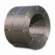
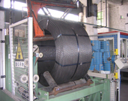
Bripac
The name commonly used in the industry to describe the steel frame, which holds and supports the coil of un strapped strand during transport and during the process of dispensing or ‘paying out’.
Competent Person
Person who an employer ensures has acquired through training, qualification, experience or a combination of these, the knowledge and skill enabling that person to correctly perform a nominated task.
Construction Work
As defined in S.3 of the Construction Safety HFC, 1999.
Dead End
The end of a tendon that is anchored in the concrete beam or slab whilst stressing takes place from the opposite end. There are two types of dead ends; onion and swaged. No stressing takes place from the dead end.
Duct (a.k.a. Sheathing)
A thin galvanized metal tube, usually oval or round, which contains the strand(s) to position and separate them from the concrete so they are free to elongate during stressing.
Employee Representative
Includes an employee member of a heath and safety committee or a person elected by the employees at a place of work to represent them on health and safety matters
Final Stress
The design stress at which stressing is complete. This stressing must not be exceeded.
Grouting
The pumping of cement grout into the duct from one end to the other
Initial Stress
A relatively low stress load that is applied to the tendons soon after the concrete has set. This initial stressed is designed to prevent or minimize shrinkage or cracking in the concrete.
Jack
The jack is a hydraulically operated piece of equipment designed to grip the strands and stretch them while bearing on the anchorage.
Live End
The end of a tendon held by wedge grips in an anchorage block, Where the tendon has two live ends, even if stressing is only carried out from one end, it is refereed to as a double live end tendon.
Mono-Strand Stressing
The system of stressing concrete members by means of applying hydraulic force to each , strand individually and progressively transferring the load to the concrete. It is often referred to as a ‘slab-system’ because it is ideally suited to the floor slabs of buildings.
Multi-Strand Stressing
The system of stressing concrete members by means of applying the load simultaneously to all strands. Multi-strand post-tensioning is mainly used in large civil structures such as dams and bridges.
Post-Tensioning
The installation, stressing and grouting of high strength steel tendons in concrete slabs and beams. The tendons are stressed only after the concrete has reached a specified minimum strength. Except in special cases, after stressing is complete the tendon is injected with cement grout which bonds the strands to the surrounding concrete over the full length of the tendon so that even if the tendon is later cut or damaged it cannot move in the concrete.
Pre-Tensioning
The process of placing concrete around pre-tensioned steel strands with subsequent transfer of the load to the concrete once it reaches a specified strength. This process is usually used in the factory production of pre-cast members such as beams, panels and columns.
Reeving
The process of manually or mechanically feeding individual strands into the duct.
Strand
A strand consists of seven high strength wires wound together into a compact group. The two sizes of strand commonly used in mono-strand stressing have diameters of 12.7mm and 15.2mm.
Stressing
The process of applying load to the strands. Pre-stressing of concrete includes pre- tensioning & post-tensioning.
Stressing Operator
Person suitably trained and nominated by the employer to operate the stressing equipment.
Tendon (a.k.a. Cable)
A group of one or more strands contained in one duct.
Transfer Strength
The minimum compressive strength that the concrete must achieve before applying the final stress.
- TENDON FABRICATION & INSTALLATION
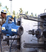
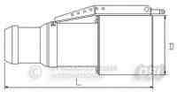
The most economical and preferred method of installation is the pushing or pulling of strand directly into the empty duct. Where strands are to be pushed, they shall be threaded and reeved into the duct one by one. The strand shall be fed into the Strand Pushing Machine from a coil of strand contained within a Bripac and then reeved into the duct. All strand reeving shall be completed prior to concrete placement. Reeving operations shall be carried out with care to avoid any damage to the strand or to the steel duct. Any damaged strands shall be rejected and replaced.
Associated Quality Assurance Documentation
Coil Identification Tag.
Strand Manufacturer Material Test Certificate.
Tendon Manufacturing Record.
Pre-stressing Installation Inspection Record.
Equipment
Angle Grinder, Bripac, Onion Jack, Staple Gun, Strand Pusher, Swage Frame.
Materials
Low Relaxation – Stress Relieved Strand (12.7mm & 15.2mm ∅).
Galvanized Sheathing (40×20, 70×20 & 90×20).
Anchorage Castings & Couplers (2s, 4s & 5s).
Anchorage Castings & Couplers (2s, 4s & 5s).
Method of Execution
- Confirm site shop-drawings are latest revision and approved for construction.
- Complete Formwork / Falsework and stop-ends for relevant pour area (By others).
- Determine Occupational Health Safety and Rehabilitation requirements with regard to installation of the pre-stressing system.
- Accept material & equipment deliveries.
- Set out location of stressing anchorages and pockets in accordance with shop-drawings.
- Slot and drill edge forms (By others).
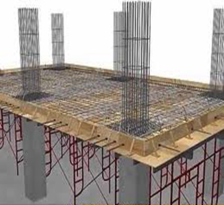
- Install cast-in anchorages as per shop-drawings.
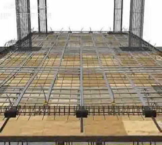
- Mark out tendon spacings and lay sheathing as per shop-drawings.
- Carefully place strand coil in Bripak prior to cutting retaining straps with tin snips. Remove and discard strapping and packaging.
- Retain the coil identification tag, noting coil Id number, and refix to Bripac
- Position coil of strand adjacent to work area and away from thoroughfares. Ensure area is of sufficient strength to support weight of coil (3 Tonne).
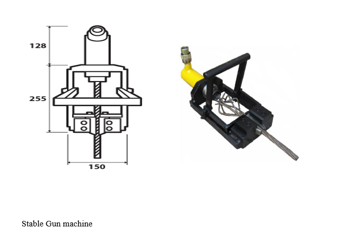
- Position the strand-pushing machine in front of the anchorage and the duct, into which the strand is to be threaded.
- Thread the strand into the wheels of the strand-pushing machine.
- Reeve the strand using the pushing machine and utilising two men, one at each end of the duct. Stand clear of strand being drawn from coil into sheathing. Do not stand between pusher and coil.
- The final (over-length or stressing-length) projection of the strand is to be checked ensuring that the jaws of the pre-stressing jack will grip the strand.
- The strand shall be saw cut at the entry end of the sheathing a minimum of 550mm from the bearing face of the cast-in anchorage.
Use goggles whenever strand is being cut.
Heat type cutting devices are not to be used to cut strand.
- Reeve strand for all tendons as per shop-drawings. At completion of all reeving operations recoil unused strand within Bripac placing cap over leading end and cover with plastic to prevent corrosion.
- Check sheathing, repair any minor damage, remove and replace if major.
- Ensure that sheathing is positioned as designed and not damaged during installation.
- Profile the sheathing in accordance with the shop-drawings & secure to anchorages and formwork so it doesn’t move during normal construction activities.
- Tape and seal the sheathing to anchorages, place intermediate grout vents to top of sheathing at high and low points as required.
- Ensure that anti-burst reinforcement is present at all anchorage locations.
- Complete final inspection of pre-stressing system and advise builder / contractor when installation is complete.
- Submit expected tendon extensions and material test certificates to builder / contractor for approval in principal (As required by specification).
- Oversee placement of concrete in and around duct and anchorages ensuring adequate compaction & vibration takes place.
- Immediately following concrete placement in a member any tendons therein shall be pulled back and forth for approximately 500mm to ensure that they are perfectly free inside the duct.
- Where the tendon has a dead-end anchorage or is coupled to a previously stressed anchorage, (the duct shall be flushed with water to remove all foreign matter immediately after the whole of the concrete has been placed in the section of the member where the tendon is located.)
- STRESSING
Description
Stressing is identified as a special process and as such all operations shall be performed by competent personnel with training and experience in this type of work and shall be carried out under the direction of a skilled Supervisor. Stressing shall not occur until directed by the relevant Engineer after determination of the concrete strength necessary for transfer
Associated Quality Assurance Documentation
Calibration certificate for hydraulic stressing equipment.
Calculations relating to tensioning force to be applied and predicted extensions of the strand elongation after release of force onto the anchorage.
Pre-stressing Record.
Equipment
Electric/Hydraulic Pump, Hydraulic Jack, Pressure Gauge.
Materials
Anchorage components; anchor head, coupling block, spacer block, barrels & wedges.
Method of Execution
- Determine Occupational Health Safety and Rehabilitation requirements with regard to stressing of the pre-stressing system.
- After form worker has removed edge forms, inspect anchorage zones and advise of any
Perceived defects in cast concrete which may affect stressing works.
- Place anchorage components, anchor head / coupling block / spacer block / barrels &
Wedges, over protruding strands.
- Clearly mark the stands with paint creating a reference point for measuring tendon
extensions.
- Check that concrete has gained the required strength (to be determined by others).
- Ensure stressing jack is accompanied by valid calibration.
- Refer to shop-drawings for stressing sequence and requirements.
- Hoist stressing jack into position over protruding strands.
- Connect hydraulic pump to jack, and pressure gauge to pump.
Initial Stress
- The application of an initial stressing load shall be carried out in accordance with the project specification and consulting engineers requirements.
- Generally, an initial stress usually only 25% of the final stress is applied approximately 24hrs after completion of concrete placement. This stressing load is applied to each and every individual strand.
Initial stress to less than 30% of final stress does not require flagging or barricades
Final Stress
- Clear area in which stressing is to take place.
Place appropriate signage and barriers around area.
- Signs stating “Caution Stressing in Progress” must be used when stressing is taking
place. Clear all areas immediately behind the stressing jack. Barricades will be
constructed from two layers of plywood.
Stress tendons to requirements of structural drawings and in accordance with
calibration report and check seating of wedges at live anchorages after lock-off.
- Final jacking force is not to exceed 85% of the minimum-breaking load.
- Ensure that stressing load is applied gradually and evenly.
- Measure & record tendon extensions, completing standard stressing record and
forward to Project Engineer for review.
After reviewing results, forward stressing reports to Client for approval by Consulting Engineer
CUTTING & SEALING
Description
Trimming of excess strand and filling of anchorage recesses in order to provide aesthetic finish and seal tendon ends in preparation for pressure grouting.
Equipment
Angle Grinder, Scrabble.
Materials
Cement, Sand, Water and Premixed Concrete.
Method of Execution
- Obtain approval of stressing results, as required by specification, from Client / Consulting Engineer prior to trimming stressing-length.
- Verbal approval should be confirmed in writing as soon as possible.
- Cut all tendons, ensuring the specified concrete cover can be achieved, using friction cutter and place off- cuts in bins provided by others.
- Wear safety goggles during all cutting operations, no heat type cutting devices are to be used.
- The sealing of anchorage recesses shall be performed immediately following cutting of the strands.
- Prior to sealing, the concrete surface of the block-out shall be trimmed and scrabbled to increase the
- Adherence with the infill mortar.
- The mortar to be used to fill the anchor Block outs shall be mixed with a minimum water/cement ratio,
- Compatible with regulations; to avoid any shrinkage cracks.
- Dry pack any edge recesses with sand / cement mix and fill “top of slab” recesses with concrete supplied by others.
- Use rubber gloves as cement may cause burns
GROUTING
Description
The pumping of cement grout into the duct from one end to the other, bonding strands to sheathing, creating a composite section and providing corrosion protection. Grouting is identified as a special process and as such all operations shall be performed by personnel with training and experience in this type of work and shall be carried out under the direction of a skilled Supervisor.
Associated Quality Assurance Documentation
- Tendon Manufacturing Record.
- Grout Sample Record.
Materials
- Type ‘A’ Portland Cement.
Equipment
- Colloidal Cement Mixer
Method of Execution
- Grout / Cement Type
- Before commencement of grouting, the total amount of required cement plus 5% for waste shall be available at the site.
- The quantity of cement required shall be established according to the type of tendon.
- All grout used for the grouting of pre-stressing ducts shall consist of Portland cement – Type A, water.
- Portland cement should comply with AS1315.
- Cement should be fresh and its temperature at time of use should not exceed 35°C.
- Any cement showing signs of deterioration, e.g. Formation of lumps should not be used.
Mixing
- Only clean water shall be used when mixing grout.
- The water/cement ratio (w/c) for grout shall be in the range 0.40 to 0.45 by weight.
- The water cement ratio should be kept as low as possible.
- Add water to the mixer first, at the rate of 8.5 litres per 20kg bag of cement.
- Any admixture being used should be mixed in with the water prior to adding the cement by uniformly dispersing it in the mixer.
- The quantity of any other additives required shall be calculated as a percentage of the weight of cement, in accordance with the recommendations of the additive manufacturer.
- Minimum mixing time should be 2 minutes.
Grouting of tendons
- Before commencing grouting, all vents/drains should be opened. These should then be closed in order, moving away from the point of injection. Close vents as grout of same consistency as that at point of injection issues.
- Grout injection should be continuous, to avoid blockages or the formation of voids in the grout column.
- Commence grouting tendon from the lowest end through standard hose connected to anchorage grout tube.
- Continue batching and pumping until good quality grout issues from vents moving away from the pump point and progressively close vents. Grout shall be bled through the high bleed point until all remnant water and diluted grout is expelled.
- At this point the operator shall discontinue pumping and wait for one minute for the grout to settle.
- Bleed tubes shall remain open and unobstructed during this period.
- Pumping shall recommence and then repeat the bleeding process.
- The injection point shall then be locked off.
- Repeat procedure for all tendons.
- The injection and bleed tubes of grouted tendons shall be checked a minimum of 12 hours after grouting. If the grout has shrunk down the tubes shall be topped up with a neat cement and water mix.
Remove grout tubes not less than 24 hours after tendon grouting is completed